This is a service manual in every sense of the word ( French and German versions of the text are included, as well as English..)
There are explanations of the mechanical and electrical functions, plenty of mechanical drawings, and the needed schematics. The quality of the scanning is excellent - all the component values are clearly legible - and very usefully there are pcb component layouts, so you can find a component on the schematic, and then very quicky pinpoint its physical location on the relevant pcb.
I cannot see how I can give this manual any less than the maximum 5 stars! Great value for money, which will pay for itself immediately. Excellent all round!
Please tell us what you think and share your opinions with others. Be sure to focus your comments on the product. You will receive $2.50 of store credit for Your review.
hat alles sehr gut geklappt. Das Servicemaual ist gut zu verwenden. Die Pläne und Schrift
ist klar und leserlich. Außerdem preiswert. Grüße an alle Hifi-Bastler
I got the manual quickly after the payment was transfered (1 day). The manual was exactly what i needed and the updates via e-mail were great. Thanx!
Text excerpt from page 55 (click to view)
31 January 1996
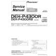
INSTALLATION PROCEDURE (COPIER)
3.2 KEY COUNTER HOLDER INSTALLATION
[I]
[C] [H] [F]
[B] [A]
A170I521.img
[G] [D] [J] [E]
A170I522.img
N CAUTION:
Unplug the copier power cord before starting the following procedure. NOTE: The Key Counter Bracket Set includes the following parts. The key counter holder and key counter should be procured locally. 1. Key Counter Bracket ......................................... 1 2. Key Counter Plate Nut....................................... 1 3. Key Counter Cover ............................................ 1 4. Bushing.............................................................. 1 5. Screws ............................................................... 8 6. Clamp ................................................................ 1 1. Open the right front door and remove the right inner cover (3 screws). 2. Remove the dummy connector [A]. 3. Remove the right cover [B] (2 screws) and small cap [C]. 4. Connect the key counter holder [D] to key counter bracket [E] with key counter plate nut [F] (2 screws). 5. Run the key counter harness [G] through the bushing [H] and right cover hole [I] and fix the key counter harness (1 screw and 1 harness clamp). 6. Install the key counter bracket to the right cover (3 screws). 7. Set the key counter harness connector to the 4P connector from the copier. 8. Reinstall the right cover. 9. Install the key counter cover [J] (2 screws). 10. Reassemble the machine.